These are just a few of the many different types of homopolar motors you'll learn how to make on this page.
A homopolar motor is an electric motor in which the current flows in one direction, contrary to most motors whose current reverses, or is commutated, at least once every revolution. While their low torque and low efficiency make homopolar motors poor choices for common use, their simplicity, adaptability and easy of construction make them perfect for technical demonstrations and science projects.
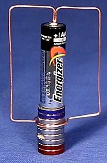
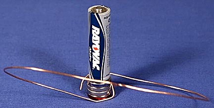
Current flowing out of the top of the battery travels across the top and down the sides of the copper wire armature. At the bottom, the wire bends toward the stack of powerful neodymium magnets at the base of the battery and lightly touches them, completing an electrical circuit to the battery. The current flowing through the lower horizontal wires interacts with the magnets' magnetic field and as Lorentz's Law states, creates a force perpendicular to both the current and magnetic field. This force pushes the lower wire away and since it's part of the armature, it's forced to travel in a circle. The direction of the force can be found using the right hand rule.
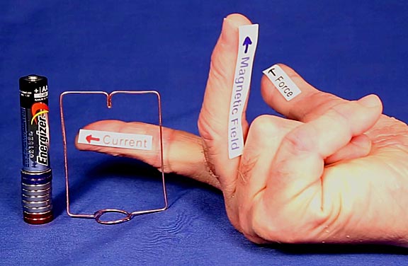
Point the first finger of your right hand in the direction of positive current flow and point your middle finger in the direction of the magnetic field, which is from the south end to the north end of the magnet. Your thumb will point in the direction of the Lorentz force. It's important to understand that the force does not push the wire in a circle. It only wants to push it away, but since the wire is mechanically constrained by the armature it has to move in a circle.
Positive current flow is used as a matter on convention, even though in reality current flow is created by negative electrons coming out of the bottom, negative electrode of the battery and traveling toward the upper, positive electrode. The reason is because Benjamin Franklin, during his days as an experimental physicist, thought the mobile charge carriers in wire had a positive charge. By the time scientists learned the truth, so many physics books had been written with the incorrect polarity and the concept had become so dogmatically intrenched that the physics community decided to retain the positive current concept. I personally believe that part of the motivation was that because most professors were right handed, they preferred a right hand rule. If negative current is being considered, Lorentz's law still works but the fingers of the left hand have to be used.
While armature shapes can vary enormously from one homopolar motor to another, they all work because of this right hand rule principle.
Hints
for Improving the
Performance
of Homopolar Motors:
Always use magnets that are slightly larger than the diameter of the battery. If they're smaller, it can be hard to get the bottom of the armature to slide down the larger battery. If they are very much larger, they limit the shape of some armature designs.
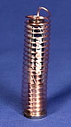
Most rare earth magnets are sold in stacks of 1/8-inch thick magnets.
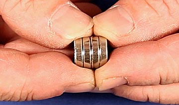
While these work, the grooves between them can cause inconsistent contact and increase drag if an armature starts riding in one. Single, thick magnets are available on-line and not only avoid these problems, but produce stronger magnetic fields for the same volume of material.
Rare earth neodymium magnets are rated in strength from N35 to N52. Always use the highest N-rating possible because a higher magnetic field translates to greater force pushing the armature.
The
dead short conditions in which homopolar motors run places extreme
demands on the battery. It's common for a battery to be completely
drained in just a few minutes. The chart below shows how several
common battery brands and models held up as they were used to drive a
homopolar shuttle, a variation of the homopolar motor.
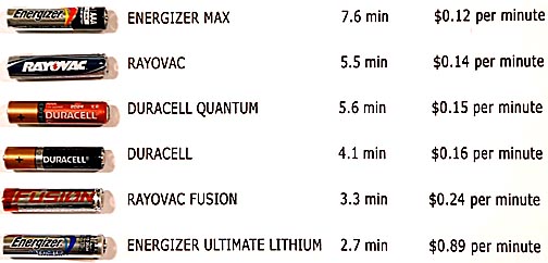
Using Energizer Max batteries may save money in the long run.
Using a nail
to tap a shallow dimple in the center of the upper button electrode
will help hold the armature on center. Just don't go too deep or the
battery may be punctured.
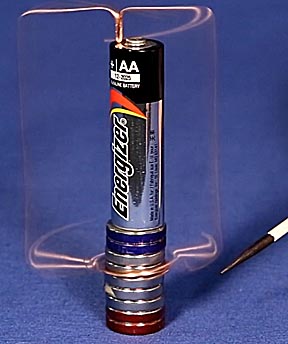
When bending
the armature, use a ruler or even draw its shape on a piece of graph
paper to make sure the design is balanced on both sides. This is
particularly important for large armature designs like the following:
If it isn't well balanced, as it builds up in speed this imbalance will throw the armature off to one side.
While almost any wire thickness can be used, very thin wires will deform at high speeds. I prefer using 18-gauge copper wire. It bends easily and yet holds its shape. Very large armatures will benefit from the use of heavier wire. Fixed armature motors, in which the magnet spins, work best with very heavy wire such as 14 or even 12-gauge.
Start by
selecting the shape of the armature. Almost any shape will work.
People have even twisted them into animal shapes so the homopolar
motor's armature looks like a carousel. The simplest, easiest and
most reliable shape is the box.
The image above shows all that's needed to form it. The bottom armature wires can be left straight and bent outward so that they barely touch the magnet to establish electrical contact. But the motor will be more stable if they are bent into a curve that very lightly fits around the magnets.
Because these motors develop so little torque, adjusting the lower contacts so that they rub firmly enough against the magnet for good electrical contact but not so hard so that their drag prevents it from rotating can be an exercise in frustration. The goal is to set them so they barely slide around the magnet. Too tight and it won't turn. Too loose and it still doesn't turn. You can go back and forth a long time before hitting on the correct amount of contact. This adjustment is by far the most difficult problem to overcome when building a homopolar motor.
Worse still, just when you think you've about gotten it, the battery has discharged.
If it seems like the tension is almost right but you can't get the last fine adjustment correct, try sliding the upper contact off the center electrode.
Sometimes the slight change in angle provides that tiny bit of adjustment required to make the motor run.
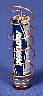
Bending the
side arms in a spiral creates an interesting and attractive pattern
as the armature rotates.
I found the lower contact harder to adjust than in the box motor. This design also rotates slower. The upper tip of the armature needs to be carefully centered and the tip itself should be cut or filed to make a sharp point. If it's cut with wire cutters and left as a two-pointed wedge, it can walk out of the holding dimple. The easiest way to avoid this is to cut it at a sharp angle.
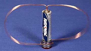
This large
loop design is similar to the box.
Because the arms are so long, they bend easily. At higher speeds the forces on them can be enough to flex them sideways and permit the armature to fall off the motor. Bending this homopolar motor's armature as symmetric as possible and using heavier wire are two ways to prevent this.
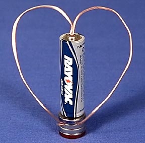
This
heart-shaped design is popular. I found it difficult to get to work
because it's difficult to bend it in such a way that it has enough
imbalance to press against the magnet for good contact.
Even when it works this homopolar motor rotates very slowly.
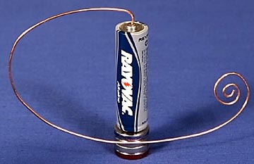
Strangely,
although this asymmetric design also uses imbalance to push the lower
armature against the magnet, it was much easier to get to work. It
still rotates rather slowly, but its unique shape makes up for this.
Most homopolar motors have fixed magnets and batteries with an armature rotating around them. It's possible to fix the armature and have the magnet rotate.
These types of motors can drive the magnet to many thousands of revolutions be minute. The problem with them is that because the magnet is attracted to the base of the battery, it's common for it to flip sideways once it gets up to speed. A stack of magnets on the base attracting the rotating magnet helps keeps it centered and aligned. Because the rotating magnet will tilt as the lower magnets are moved, it's possible to use them as a fine adjustment by moving them to control the amount of contact with the armature. This design requires are very stiff armature to prevent the rotating magnet from starting to bounce on it. A flat headed screw is placed on the center of the rotating magnet to act as a low friction needle bearing.
One of the stranger designs is the bouncing homopolar motor.
In this version, wind the armature as you would for a spiral motor, but place the loops as close together as possible. This increases its vertical flexibility. When current flows through the coil, a magnetic field is created inside it which, if the magnets are placed properly, will be repelled by them. The coil will be pushed up, electrical contact broken, the magnetic field collapses and the coil drops down to reestablish contact and the cycle repeats. The bouncing can happen several hundred times a minute.
The homopolar
train operates on the same principle.
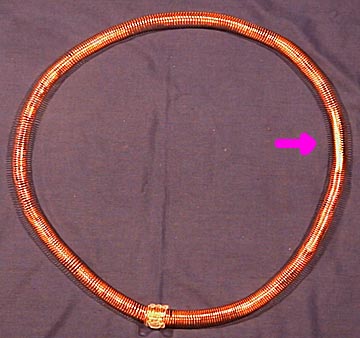
A battery with magnets at both ends speeds around the inside of the long coil. Here's how it works:
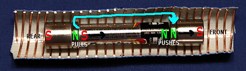
This cut-away view shows the train inside its track, which is a coil of copper wire. The "train" consists of a battery with a rare earth super magnet at each end. The magnets are oriented so that they want to push each other apart. The battery holds them far enough apart so that their attraction to the metal ends of the battery is stronger than their mutual repulsion. In this example the north ends of both magnets face each other. The train will also work if the south poles face each other, though it'll run through the track in the opposite direction. Electricity flows out of the battery, through the magnet at one end, into the bare copper coil (as indicated by the cyan arrow,) into the magnet at the other end and back into the battery. As the current flows through the coil, it creates a magnetic field, which opposes the magnet in the front of the train (the two green Ns) so it pushes the magnet away. At the rear of the train the opposite happens. The South end of the field attracts the North end of the magnet and pulls the train forward. So the train gets two forces speeding it around the track: the pushing force in the front and the pulling force in the rear.
Tracks for these trains can become quite complicated. For more information about them, please click here: How to Build the Simplest Electric Train.
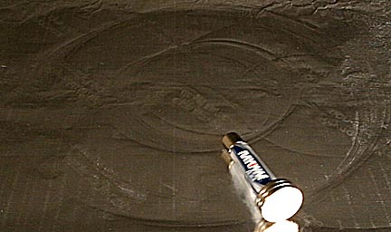
My favorite homopolar motor is the rolling battery design.
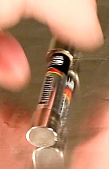
Place a magnet at each end of a battery so that the ends of the magnets want to push themselves apart. Place this unit on a piece of aluminum foil on a very flat surface and the battery will roll. The area of foil directly under the battery acts as the armature. Current flowing through it can't push the foil away, so since every force has an equal and opposite force, the foil, or more properly the current flowing through it, pushes the magnets forward making them and the battery roll. The concept is similar to the rail guns the military is developing as weapons.
Even more fun is putting larger magnets on one end of the battery to make it roll in a circle.
This page should have presented enough information to get you started building your own homopolar motors. I hope you found it useful or at least entertaining. Thank you for visiting!
If you'd like
to see some of these motors in operations, please click on the
following link:

Return to my main page to browse 60 other subjects