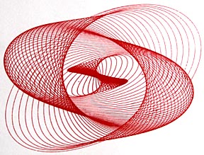
While drawing machine HARMONOGRAPHS like this:
...can create beautiful patterns such as the following:
The flexibility that enables them to make such complex images also makes them so difficult to control that reproducing an image is almost impossible. Repeated web searches finally turned up a device by professional photography Paul Wainwright (www.paulwainwrightphotography.com) that not only provides the control needed but also produces images directly to digital media. I've named my version of Mr. Wainwright's pendulum-based drawing machine a Pendulight.
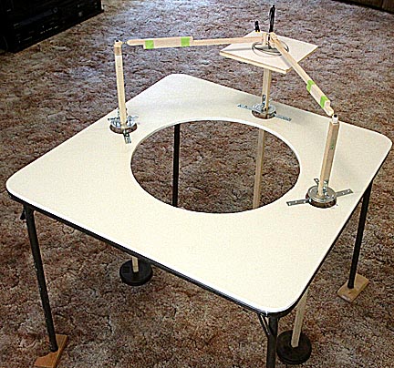
My Pendulight drawing machine
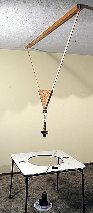
This drawing machine, which i call a pendulight because it combines a pendulum with a flashlight, consists of a slower upper pendulum, a faster lower pendulum hinged to move perpendicularly to the first pendulum, a flashlight covered with aluminum foil with a pinhole in it and a camera into which the light from the flashlight shines. If the construction looks rough, that's because it was built of bits and pieces found around the house. The only odd piece is the card table with the large hole in it. That's the same table used for my harmonograph. Normally the table is elevated so that the edge of the hole is at the same level as the flashlight. This lets it function as a guide to the magnitude and angle of release, two important aspects of controlling the shape of the image to be produced. However, it isn't essential. The turnbuckle in the lower pendulum allows its length, and therefore period, to be adjusted. Larger changes in length are made by bolting pieces of metal strapping to the top of the piece of metal strapping used to hold the flashlight.
How it works is that in a pitch black room, the flashlight is turned on, the pendulums started swinging and the camera's shutter locked open. As the flashlight moves back-and-forth and side-to-side, the light from the pinhole traces out a line that's recorded by the camera. Leaving the shutter open for one to two minutes produces a complex pattern of closely spaced lines which, under the right circumstances, can result in a very attractive picture.
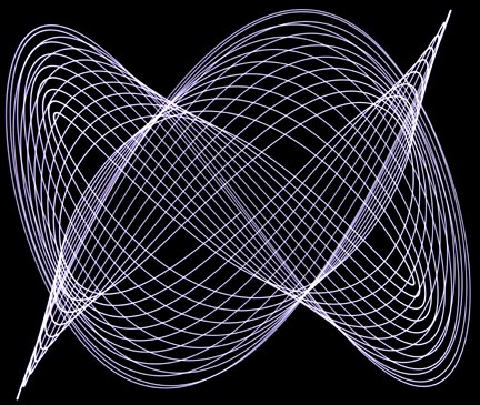
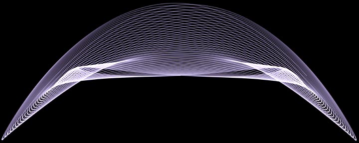
Those 'right circumstances' occur when the ratio of the periods of the upper and lower pendulums are whole number ratios of each other, such as 2:1, 3:2 and 4:3. The image above shows the pendulums in the 2:1 position. The upper pendulum is 31 inches long and the lower is 12 inches long. This configuration results in the upper pendulum have a single cycle period of 2 seconds and the lower pendulum 1 second, hence 2:1. When they are near this point many interesting images can be produced. Further away the images become jumbled. We'll take a closer look at how the ratio of periods affects images later. First, though, there are a couple of issues that need to be addressed.
If a dimming LED flashlight is used and not set at maximum power, the resulting trace will be a series of dots rather than a solid line as the following image exemplifies:
The reason is that LED flashlights create a dimming effect by pulsing the light on and off very quickly. Unless this is a look that's desired, it's best to always use the flashlight at maximum power. Another problem shown in the photo above is the bright zone near the center of the pattern. This is caused by the flashlight's lens, or reflector, beaming focused light directly into the camera's lens. Placing a piece of white typing paper between the lens and foil eliminates this problem.
A third issue is using string or wire for the pendulums. Doing so allows the flashlight to twist. If the pinhole isn't in the exact center of the rotation the lines won't be evenly spaced. The following image shows this:

Using rigid pendulums eliminates this problem.
The flashlight in my pendulight drawing machine is rated at 2000 lumens, though I suspect it's putting out only half that. Setting the camera to ISO 100 at f8.0 provided good exposures.
The first time you fire up a pendulight, the odds are you'll get a mess like this:
This is typical for patterns produced far away from the resonance point. In this case the lower pendulum is too short. It's about 1.5 inches above the resonance point. The following sequence of images shows how the images become more organized as the lower pendulum approaches the 2:1 ration of periods:
Here the upper pendulum has been lengthened 1/2 inch and the image is already presenting a more oranized appearance.
Adjusting the turnbuckle to increase the lower pendulum's length by another half inch greatly increases the amount of order.
One quarter inch longer and we're almost there.
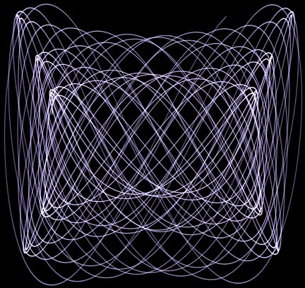
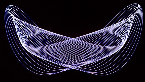
And here we
are at resonance. Ideally, this should be a single line in the shape
of a "U." But, imprecisions
in the
alignment of the pendulums created some crosstalk between them
resulting in image filling.
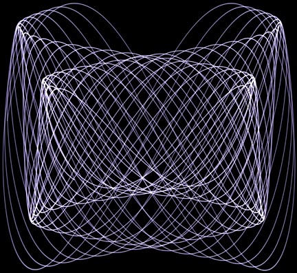
Lengthening the lower pendulum a quarter inch below the resonance point produced this image.
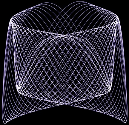
Adding a full inch gets us into the jumbled regime once again.
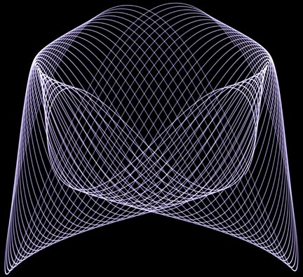
I find that the most interesting images are produced either right at or just below the resonance point.
Besides changing the ratio of the pendulum's periods, images can be sculpted by varying the angle at which the pendulum is released. In the following discussion the upper pendulum swings along the 0-degree line and the lower along the 90-degree line:
The middle image below is back at the resonance point. It was created by releasing the pendulums at a 45-degree angle so that both pendulums started off with the same amount of deflection. The image on the left was created by changing the angle to 22 degrees, in which most of the deflection is taken up by the longer upper pendulum. The one on the right came from releasing at 67-degrees, where the lower pendulum gets most of the initial deflection.
As these images show, release angle has an enormous affect of the shape of the image.
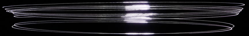
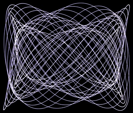
Another way to change the image is by varying how long the shutter is held open.
From left to right above: the shutter was left open for 30, 60 and 120 seconds. Note that this technique not only increases the amount of line fill, but introduces completely new shapes and details.
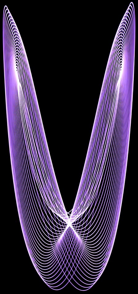
All of the above images were created around the 2:1 period ratio. The following series of images show what happens when the lower pendulum is lengthened to 20 inches and we work our way downward toward and then past the 3:2 resonance point:
Here's what
resonance at the 3:2 point looks like.
It makes me
think of a worm tying itself into a knot.
Extending the lower pendulum to 36 inches enables us to get the 4:3 resonance point.
Look carefully
and you'll see that it's similar to the 3:2 resonance image
except that
the worm has added an extra pair of loops to his knot.
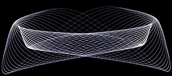
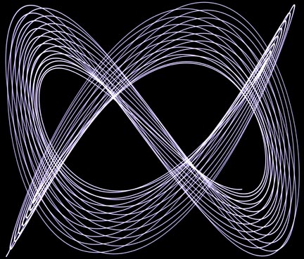
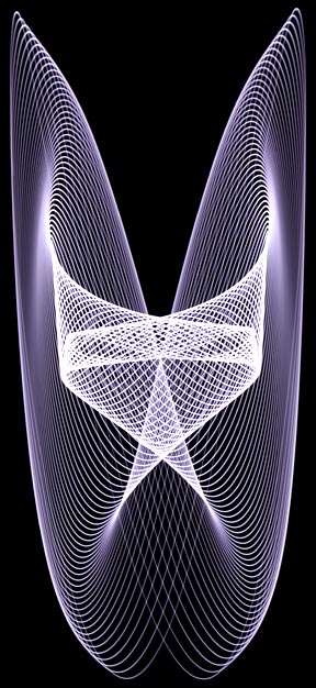
While the 3:2 and 4:3 points can produce interesting images, I find them to be too convoluted to be attractive. For that reason I prefer to work around the 2:1 point. Here are some examples:
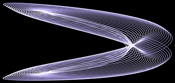
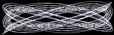
The above two
images are the same. The only difference was that the lower image,
which makes me
think of a flying saucer or an art deco crab,
was released
at 25 degrees instead of 45 degrees.
Look carefully
and you can see that the same
features are
present, but stretched out sideways.
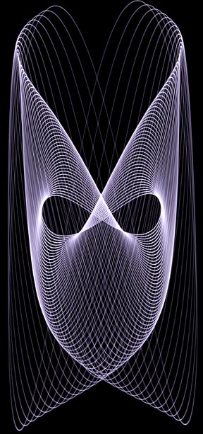
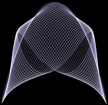
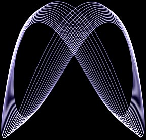
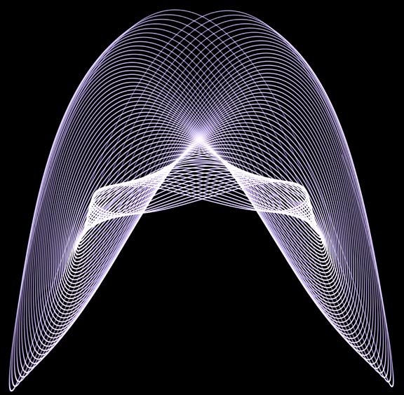
This looks like a mask to me. But, turn it upside down and you have...
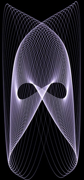
...a Viking helmet!
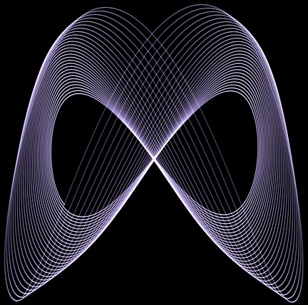
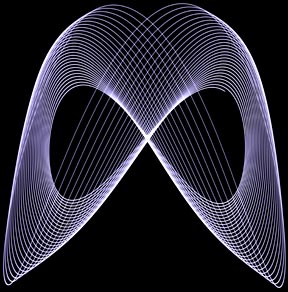
The upper wings of this pattern reminds me of the collar of Maleficent's cloak in the 2014 movie of the same title.
I feel that adding color in post processing distracts from the simple elegance of these images.
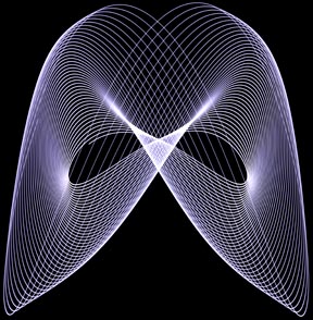
Except,
perhaps, in the case of this art deco butterfly. The image was
created by using a 22-degree release angle.
I think it
would have benefited from an angle closer to 30 degrees to widen the wingspan.
For visitors preferring a live action presentation of this page, please view the following YouTube video:
I hope you enjoyed this page. Building a pendulight drawing machine is easy, inexpensive and interesting. I sincerely hope you'll give it a try. Thank you for visiting this page!

Return to my main page to browse 60 other subjects