Pintographs How to make and use pintographs.
Pintographs
are harmongraphs that use
electric motors instead of pendulums to move a pen to create
fantastically detailed and beautiful line drawings. They come in two
basic forms.
 ........
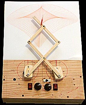
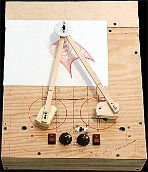
Straight
Arm Pintograph .................................Scissor
Arm Pintograph
Each produces similar images. The main difference is the the scissor arm type amplifies pen movements to produce larger drawings. It's possible to have several sets of arms for a pintograph so they can be changed out to create whatever design is wanted. (I offer no apologies for the rough appearance of this drawing machine. It's gone through many modifications and shows the scars of previous incarnations.)
Lines drawn by harmonographs show separation between strokes because the pendulums are slowly running down and the pen moves less with each swing. Lines drawn by pintographs show separation because the two motors run at slightly different speeds so the pen is constantly being pushed along different paths. However, with pintographs the faster motor will eventually catch up to the slower one so the figures repeat if the machine is left to run long enough. These machines can be compact and can easily create copies of previous images.
How
To Build A Pintograph:
Pintographs consist of two motors, switches, a speed controller for at least one of the motors and some sort of linkage system connecting the rotating shafts of the motors to a pen.
The first pintograph I made used inexpensive toy gearmotors from a hobby shop. It failed completely. The motors didn't have enough torque to drive the pen and were so irregular in their RPMs that the drawings looked like a mess of spaghetti. On the recommendation of Mr. Fran McConnville (http://www.fxmtech.com/harmonog.html) I upgraded to a pair of RZ12-300-10RPM gear motors ($25 each) from servocity.com and a MX033 DC motor speed controller ($22) from Carl's Electronics (www.electronicskits.com). The result was a much more robust drive system that produced clean images.
Here's a view of the back:
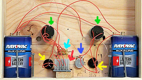
Two 6-volt lantern batteries connected in series provide 12 volts to drive the motors. Many pintographs use AC power supplies but I wanted something that didn't need to be plugged in to a wall socket. The batteries have supplied over ten hours of continuous operation and aren't showing any signs of running down. The green arrows indicate the two gearmotors. The yellow arrows are the on/off switches, the red arrow shows the controller for one motor, the blue arrow a 0-25 ohm potentiometer for small adjustments to the other motor and the cyan arrow points to a switch that lets me reverse the direction of one of the motors. This switch is important because some images are produced with both motors rotating in the same direction while others look best if the motors rotate in opposite directions.
The basic circuit is very simple. One motor is connected to the batteries through an on/off switch and the potentiometer. The other motor is connected to the batteries through its on/off switch, the reversing switch and the speed controller.
The front of the unit looks like this:
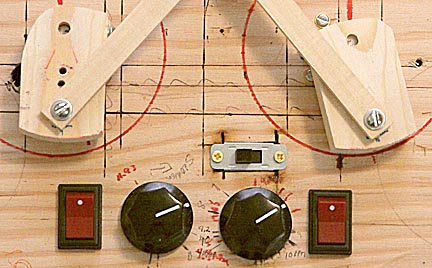
The red on/off switch on the left and the potentiometer next to it control the left hand motor. The red on/off switch on the right, the dc speed controller knob and the slide (reversing) switch above the knob control the right hand motor. The switches, knobs, and potentiometer came from Radio Shack.
The armatures attached to the drive shafts of each motor are 2-inch long pieces of pine 1x2 lumber. Most pintographs use disks on the motors.
The arms connecting the motor armatures to the pen are made out of 1/4 x 1/2 inch basswood from a hobby store. Michael's craft stores also carry it. The motor drive shafts are 5.25 inches apart and the primary drive radius, where the arms attach to the armatures, is 1.75 inches. The armature on the left motor has several holes drilled at various radii so the drive radius can be changed to create different designs. The minimum arm length from the pivot on the motor armature to the pivot near the pen is 3.25 inches. Any sorter and the arms may lock up when the motor armatures are both pointed outward.
Scissor arm configurations have enough play in them so that with just a little weight on the end there's sufficient contact between the pen and paper for the pen to draw lines. Straight arm pintographs can be so stiff that even with several ounces of weight the pen won't always touch the paper. The solution to this is to build a hinge into each arm. Mechanical hinges can be used but are usually too heavy and have so much play that odd wiggles show up in the traces. My solution was to use a thin piece of stiff, flexible plastic taped to the ends of the arms where they've been cut in half.
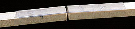
Stationary stores sell clear plastic binder sheet covers that work very well. A free source is the thin, clear plastic used to encase many items sold in stores. The strips only need to be two inches long and half an inch wide. I've experimented with poster board but it tends to tear.
The pivots between the arms have to allow easy rotation of the arms yet be tight enough so that they don't wiggle back and forth. A very cheap solution is to drill matching holes in both pieces of wood then thread a short machine screw into the one to be allowed to pivot and over tighten it to strip the threads. Repeat this a few times until the screw can be pushed into the hole without having to be screwed in. Force the screw through that hole and screw it into the hole in the other arm or the armature. Don't over tighten it this time. The screw will be locked firmly in place in the second hole while the top arm can pivot freely.
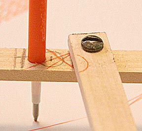
In the image above the stick on top is the one that's had its threads stripped and is free to rotate yet is still held snuggly by the screw. A metal washer between the to arms facilitates free movement. Don't over tighten the screw. There needs to be a few thousandths clearance to allow the upper arm to move.
This image also shows a simple pen holder: a hole sized to match the diameter of a pen cartridge. Properly sized, it holds it much tighter than most clamps. Another advantage is that by drilling through both arms at the pivot the pen will be centered on the pivot point, which helps create symmetric traces. This pen holder also makes it easy to drill holes above and below the pivot point for greater flexibility and creating unique traces.
I prefer using 0.7 mm gel pens by Uni Ball drawing lines on Kodak Ultra Glossy photo paper. They run with very little drag, have a wide range of colors and last a long time. Be warned that some glossy papers will clog Uni Ball Gel Pens.
How
To Use A Pintograph:

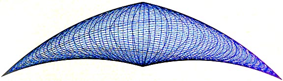
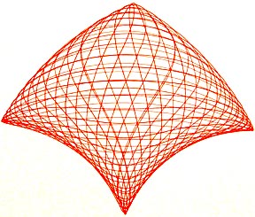
Typical pintograph image.
Creating clean traces like the one above requires a few simple tricks. First and most important, do a test run to make sure the pen is putting down even, uniform lines throughout the trace. Some pens skip or leave blots. If there isn't enough weight on the pen areas of the trace will be light or even missing. Too much weight and the pen can lay down ink that's pushed out to the sides leaving two thin lines rather than a single solid one.
A practice trace also shows where the darkest areas are, where the pen lays down many lines in a small area. Select one of these areas to start and stop the pintograph. This prevents hanging lines, lines whose ends can be seen.
It's critical to select the proper difference between the speeds of the two motors. If the difference is too great the lines will be so far apart the parallel lines won't appear to flow from one area to another. Too close and the lines will lay almost on top of each other and you'll end up with a solid mass of ink. Also, if the traces are to close subtle irregularities will be obvious and unattractive. The optimum speed difference varies from trace to trace. Small traces, or designs, may require a greater motor speed difference to avoid having the lines overlap too much. Larger designs can tolerate very small differences in motor speed without appearing too crowded. Doing a test run is essential for determining the proper speed difference. Understanding how the speed difference works to create a pintogram is necessary estimate what speed difference to select.
Imagine a pintograph with both motors running at the exact same speed. They're going to be synchronized at all times so they will push the pen over and over again along the same path. It might be a circle, and ellipse of a more convoluted shape depending on the initial starting positions of the arms, but it'll still be a single solid line. Now image that one motor is adjusted so that it rotates one-tenth of a revolution faster than the other motor. The pen starts at point "A" but this time after the unchanged motor completes a single rotation the other motor will have completed 1.1 rotations. Consequently the pen won't end up at the same place it started. After the first motor completes a second revolution the second one will have completed 1.2 rotations and so on. After the first motor completes 10 rotations the second one will have completed 11. But, because the second motor has jumped ahead one full rotation, it will be back in sync with the first motor and the pen, having now traced ten lines, will have found its way back to its original starting point. It's like a car race. One car is slightly faster than another so it pulls ahead a little each lap. After enough laps it catches up the the car it was pulling away from by coming up along side it from behind. It's the same thing with the motors. One pulls ahead a little each revolution until it catches up to the other. Let's call this "completing a full cycle."
That's what happened in the image above. The pen started in the dark point near the bottom, followed a complex pattern that took about 60 traces and at the end of its complete cycle ended up back at the dark point in the bottom corner, which is when I turned off the motors. The question is: How much of a speed difference is best?
The answer is for pintographs similar in size to the one on this page and for most drawings you want one motor running around 10 RPM and the other at 9.7 RPM. The problem is that determining RPMs is awkward. A much easier way to set the speeds is to use a stop watch to measure how long in seconds it takes per revolution. Draw a line on the armature of each motor and another line on the surface on which the motor's mounted. With the motor running, as the armature line swings past the stationary line start the stop watch. Stop it when the armature's made a complete rotation, as indicated by the lines passing each other a second time. It's very easy to get within 0.1 second or better. Do this for each motor. The reference motor should have a single rotation time close to 6.0 seconds. The adjustable motor should be set so its time is around 0.2 seconds longer or 6.2 seconds. The longer time reflects the fact that it's running slower. If the test trace ends up looking too crowded, decrease the speed of the adjustable motor to 6.4 seconds and try again. Repeat this until an attractive trace results.
These are the fundamental techniques for creating pintograms. Next we investigate how changing rotation direction, pen position, rotation radius and arm length affects the final drawing. We'll start of with traces created by a straight arm pintograph.
Rotational
Direction:
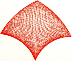
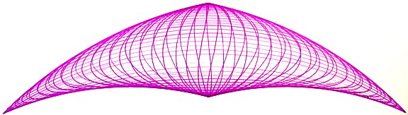
The first pintogram for consideration is the simplest. Both rotational radii are 1.75 inches, the arms are both 4.25 inches long, the pen is located at the arms pivot point and the difference between the motor's rotational speeds is 0.18 seconds. The first trace is with both arms rotating counter clockwise.
This arrowhead profile is the basic shape of all pintograms. It is distorted by changing arm lengths, rotational radii and pen location relative to the arm's pivot point but they are all still similar to it. The four corners correspond to specific armature locations. The top corner occurs when both armatures are pointing straight up. The bottom corner happens when they are both straight down. The left corner is made when the left armature is pointing in the 4 PM position and the right armature is opposite that, toward the 10 PM direction. Finally, the right corner is drawn when the right armature is pointed in the 8 PM direction and the left toward 2 PM. Knowing this helps to start a trace in one of the corners, where initial irregularity won't be noticeable.
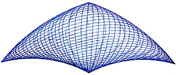
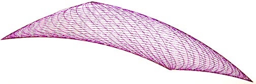
The next pintogram has everything the exact same except the direction of rotation of the right hand motor is reversed so that it is now rotating clockwise. In other words, the two motors are turning in opposite directions.
While the shape is the same, it's shocking how much higher the line density is. In fact it's so high that many irregularities in the trace can be observed. I repeated this experiment a second time being careful to measure the rotational speeds of both motors to make sure that reversing the direction of the one motor didn't change the differences in rotational speeds. It didn't. Even more surprising is that the designs are created differently. In the first trace all the lines are created symmetrically left to right. In the second the pintograph draws the right side first then works it's way across the drawing to trace the left side.
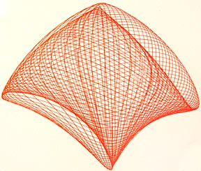
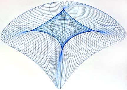
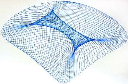
I couldn't believe the magnitude of the difference from merely reversing the direction of the motor so I tested it again, this time with arm and radius lengths set to create a completely different shape. (I'll explain shortly how these traces were created.) Here's what I got:
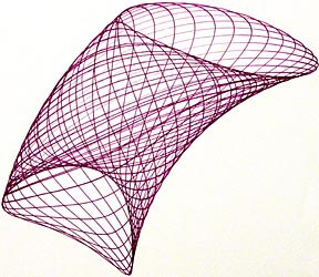
Both motors rotating in the same direction.
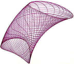
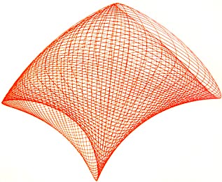
Motors rotating in opposite directions.
The same thing happened. To my eye the designs created when the motors rotate in opposite directions are more attractive.
Arm
Length:
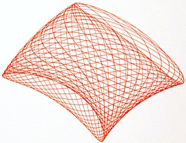
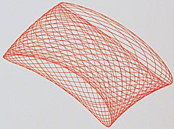
The following three images show what happens when both arms of a straight arm pintograph are increased:
4.25-inch long arms, actual trace was 5 inches left to right
6-inch long arms, actual trace was 8 inches left to right
12-inch long arms, actual trace was 14 inches left to right
Increasing arm length does two things: it stretches the image left and right and compresses it top to bottom. The next question that begs to be asked is what is the effect of increasing only one leg.

Left arm 10.5-inches long, right arm 12-inches long.
Uneven
arms elongate the trace on the side of the shortest arm and rotates
the image away from the centerline of the pintograph toward the side
of the shorter arm.
Arms equal in length, left armature radius reduced to 1.5 inches.
Reducing
the radius of rotation of the left hand armature squashes the image
towards the right.
Pen
Position:
The position of the pen relative to the pivot point at the end of the arms has an enormous influence on how the trace looks. This is a particularly important issue because almost all pintographs have their pens held in clamps that are slightly offset from the pivot. The following five designs were made with the pen first inside the pivot point, then at the pivot point, and finally three positions further away from it. Although reduced in size from the original traces the images reflect the change in size as the pen position is moved.
In
the pintogram above, the pen was located 5/8-inch inside the pivot
(closer
to the motor.)
Here the pen is at the pivot.
5/8-inch
outside the pivot (farther away from the motor)
This
looks a lot like the first image, but in fact that image leans to
the left slightly whereas this one
leans
to the right. Also, the light areas of crosshatching have their
densities reversed.
1.25-inches beyond the pivot point.
2-inches beyond the pivot point.
Note how the design takes on a tube-like appearance when the pen isn't located at the pivot point. You can also see that they all reflect the original arrowhead shape, though it becomes very distorted. In all of these traces the pen was moved along the right hand arm. This creates the somewhat confusing situation that when the pen is beyond the pivot point it's to the left of the left hand arm.
Effects
of Changing Armature Radius:
Drilling several holes along the radius of the armature allows us to investigate the effect of varying the radius of rotation driving one arm. All of the following image were made with the pen located 5/8-inch outside of the arm's pivot point of the arm on the right. The armature on the left was the one whose radius was varied.
Radius of rotation = 2 inches
Radius of rotation = 1.75 inches
Radius of rotation = 1.5 inches
Radius of rotation = 1.25 inches
Radius of rotation = 1 inch
As
had might have been expected, reducing the radius of the left
armature has the effect of compressing the image along an imaginary
line from 7PM to 2PM.
Scissor
Arm Pintograph Designs:
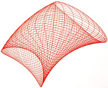
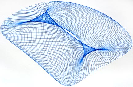
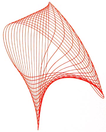
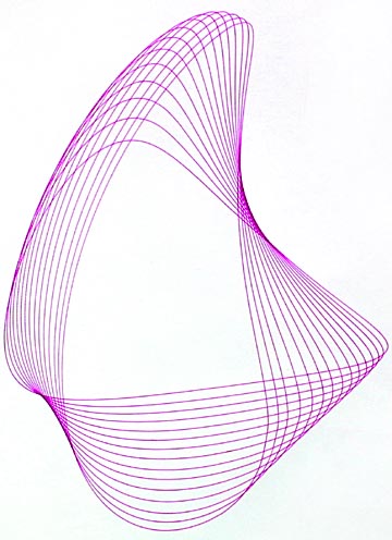
Scissor arms not only enlarge pen movements in the same way as pantographs enlarge drawings, they also create designs that can be radically different from anything produced by straight arm machines. In the following three images the scissor arms had 4.25 inches between each pivot, the motors rotated in opposite directions and the pen was located 5/8-inch to the left of the final pivot, creating a slight asymmetry to the images.
The image above was drawn with both radii of rotations set to 1.75 inches.
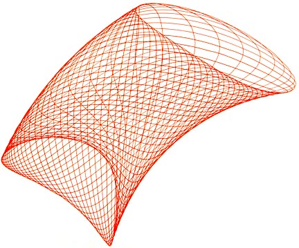
For this image the radii of rotation of the left armature was reduced to 1.5 inches.
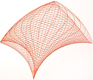
To create this last image the radius of the left armature was set at 1 inch.
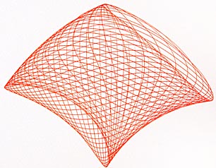
Partial
Cycles:
All of the figures so far have been of full cycle traces. One last way to create a wider variety of designs is to stop the drawing before a cycle has be completed. By carefully selecting the start and stop points many additional shapes can be created. The following two images demonstrate this technique. The first is from a straight arm pintograph, the second from a scissor arm type.
 .......
Final Words:
Pintographs come in a wide array of drive systems and arm linkages, each creating unique images. This page offers just a small sample of the design possibilities for these wonderful machines. I hope you found it helpfull.
NEW!!!
Mr. Joe Freedman has opened a kickstarter project for a new drawing machine. I highly encourage anyone interested in such machines to pay his page a visit at:
http://www.kickstarter.com/projects/1765367532/cycloid-drawing-machine
Please note: I have not used Mr. Freedman's machine so I can't endorse investing in it or even purchasing one when they become available. Having said that I also have to say that I've requested to be put on the potential purchaser's list as soon as it's available.
![]()
Please click here to go to my homepage and browse 100 other topics.