TELESCOPE MAKING
The following articles document some of what I've discovered over the last fourteen years of telescope making. Many of them are reprints of articles that have been published in various telescope making magazines.
(Click on main site to browse 70 other topics ranging from exotic kaleidoscope designs to the strange world of lucid dreaming.)
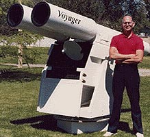
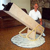
The telescope I use is a binocular with eight-inch f8 mirrors for objectives. Originally, it was mounted on the motorized mount pictured above that the observer sat in. It gave the impression of flying through the heavens. However, this system, featured in the July, 1996 issue of Sky & Telescope magazine, was too bulky so it has been remounted in a conventional dobsonian mount. Here's what it looks like now:
This newer version may not look as sexy as the motorized chair but it works better and is a lot easier to transport.
Topic List:
NEW!!!
3D
image recommendations
NEW!!!
Introducing
the "Crisco Mount!"
Ultra-thin
flexed-mirrors
A
Foucault tester made from scraps
Dot
masks for Foucault testing
How
Martha Stewart almost cured my telescope of stiction.
Flush-valve focuser
Think mittens!
80 MM
binocular dew shields
Make a giant Planisphere
A great dust
cover for mirror making
Prescription eyepieces
Wire spiders
The blackest
black for lining telescopes
Black
velvet: is it worth it?
Coated vs
uncoated observing glasses
The wire test
Conquering the
Foucault zone of uncertainty
Beware of
collimation dots
NGC object sizes
Make your own
ronchi gratings
A failed
attempt to make an off-axis paraboloid
NEW!!! 3D image Recommendations
An interesting adjunct to astrophotography is to convert photos into three dimensional image pairs. When viewed properly these create a realistic 3D images. While researching for a webpage on this subject for THIS AND THAT, I discovered that many such image pairs available on the Internet were made incorrectly. The most common problem was with Mars, as the following two image pairs show: (For instructions on how to view these images please open the HOW TO MAKE THREE DIMENSIONAL IMAGES page.)
Here's what it should look like:
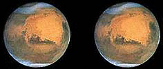
The next image of Mars looks similar, but examine the 3D-image carefully and you should see that it actually looks like the image was painted on the inside of a bowl instead of the outside of a sphere. The reason is that the image on the right should really be on the left.
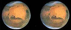
The difference in the two pairs is that the first one has the planet in the right hand image rotated slightly to the left. This creates a bulging-out appearance as is needed to give the impression you're looking at a sphere (Again, please see the HOW TO MAKE THREE DIMENSIONAL IMAGES page to read why this is so.) The second image pair has Mars rotating to the right on the right hand image so it creates a bowed-in or concave look.
Jupiter is another frequently reversed subject for 3D image pairs. Here's how it should look:
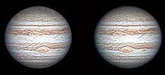
Note that the right hand image clearly shows that the red spot has rotated slightly to the left, creating a bulging-out impression.
Another common error occurs in artistic manipulations of pictures of galaxies. Look at the following image pair of M81 and see if you can spot the problem:
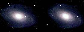
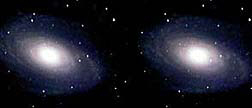
This can be a difficult image to see in 3D so don't be discouraged if you can't get it right off. What you will eventually notice is that the stars have be shifted in such a way that they appear to be behind the galaxy. Since all visible stars are obviously in our galaxy, such an image is impossible. I believe it must have been done in an attempt to make the galaxy stand out more. Shifting the star positions so that they look like they are in front of the galaxy is more accurate, as the following pair shows:
For some reason I don't understand, I find this second image pair much easier to view.
The difference between the first and second set is that in the first the stars in the right hand image were shifted to the right, making them appear further away than the galaxy. In the second pair the stars in the right hand image were shifted to the left, making them appear closer.
NEW!!! Introducing the "Crisco Mount!"
Let me apologize right up front because things are about to get a little weird. (Please don't think the rest of the articles on this page are as frivolous as this one.)
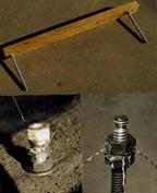
I had an idea for a mount where the altitude discs rolled on a soft material that would hold the scope in any position. Azimuth adjustments would be made by sliding the entire scope rotationally left or right as needed. The altitude bearings would be be fixed to the telescope tube in such a position and be of such a size so that their centers coincided with the center of gravity of the scope. (I'd seen a mount like this years before and it's simplicity appealed to me.)
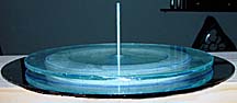
I experimented with many materials for the base the scope would ride on, (carpeting, several foam rubbers, plastic, etc) but none provided the combination of smooth motion yet held the scope's position. Then the solution hit me: slather a thick layer of Crisco (the cooking shortening) between two layers of thick polyethylene sheeting. The smooth plastic would enable sliding and the Crisco would be squashed by the altitude circles creating divots that would hold the scope. Here's what it looked like:
It worked! But... walking on it while viewing was like walking on oil-covered ice: my feet felt like they were always about to slip out from under me. Additionally, from time to time I'd step on a thicker section of Crisco and it would make a disgusting oozing sound that would be embarrassing at a star party. I decided this was one idea that didn't pan out.
The telescope I used for this mount was rather novel in itself, it was an unobstructed, f9, 6-inch off-axis paraboloid. (Not a Hershelian, this scope didn't use a symmetric paraboloidal mirror tilted to the side.)
![]()
Ultra-thin
flexed-mirrors
(A
great idea that didn't work so great)
While working with the very thin (1.25 mm) first surface mirrors used to make kaleidoscopes, it occurred to me that since they flexed so easily it might be possible to develop a way to warp one so that it would serve as the primary for a telescope.
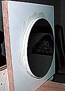
The first step was to cut an 8-inch diameter circle out of the mirror material and mount a puller plate on the rear. The puller plate was double thickness glass with a hole drilled in the center. It was attached to the back side of the mirror using double faced mounting tape. The tape was cut so that it formed a ring 1 inch across with an inside diameter of 4 inches and an outside diameter of 6 inches. A 6x32 bolt was fed through the hole in the puller plate before the plate was attached to the mirror.
This assembly mounted on a flat (carefully tested to make sure it was) piece of malemine that had been cushioned with a 1/2-inch ring of foam rubber. The screw through the puller plate passed through a hole in the center of the board. Tightening a wing nut on the end of the bolt sticking through the back of the board held the mirror against the rubber ring and pulled the face of the mirror toward the board, flexing it into a rough parabola.
When I tested the mirror it was obvious early on that this was an idea that wasn't going to work. The image was astigmatic, probably from unevenness of the support and puller rings and the mounting board and puller plate not being perfectly flat. These are problems that could be worked. The one problem that I couldn't solve was surface ripple. As the following partial foucaultgram shows, the surface of the mirror had a series of parallel ripples flowing across it's face, most likely the result of its being float glass.
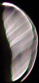
I'd hoped that the higher quality of glass used for making first surface mirrors wouldn't have ripples in it. In this I was wrong.
But, I'm not disappointed because even if the idea didn't work by publishing it here I may be able to prevent someone else from making the same mistake.
A Foucault tester made from scraps
Ten years after I thought I'd made my last mirror I came up with a different way to make them. The problem was that I'd long since thrown away my Foucault tester. Impatience to have one right away and a reluctance to spend money to purchase one drove he into the garage to see if I could widget one together from bits and pieces I had on hand. Two hours later I'd accomplished two things: made a Foucault tester for free and completely trashed the kitchen I built it in. Here's what the tester looks like, I leave it to your imagination to picture the kitchen:
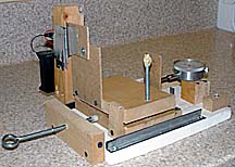
I was able to
use a piece of plywood for the base, some MDF for the
moving
carriage and tilt base knife edge tilt table, and a few bits
of 2x2 pine to
hold the slit and lamp.
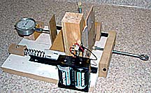
The hinge for
the knife edge tilt table is a small piece of aluminum
flashing
stapled to the side of the carriage base and tilt table.
The only
innovations were the use of an old (23-year) dial
indicator to
measure the knife edge position and putting
the spring
used to keep the carriage pushed against
the adjusting
screw on only one side. I had one one
each side but
the carriage shimmied side to side
throwing the
readings off. Putting the spring
on one side
kept it tight to one guide rail,
which stopped
the shimmying.
I'll be the first to admit that it's not the prettiest tester ever made, but it reads consistently to less that 1/1000 of an inch so I'm very happy with it.
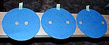
Dot masks for Foucault testing
I have always had a problem with using Couder masks for Foucault testing: diffraction effects distort the shadow patterns so much that making side-to-side comparisons is difficult. I found it was much easier to make a series of separate masks, one for each zone, out of black construction paper with two, 3/4-inch diameter holes cut into it to make a mask for testing that particular zone. The combination of only having one zone visible and the simple round geometry of the opening, unlike the complex curved openings of the typical Couder mask, makes it much easier to locate the knife edge position where the shadows are equal.
How Martha Stewart almost cured my telescope of stiction
Stiction is the word that refers to the stickiness Teflon bearings have because of the difference between static (always larger) and dynamic friction. This difference is what makes tracking at high power difficult. It requires more force to get the scope moving than it does to keep it moving. The result is that the scope first resists moving, then suddenly breaks free and charges past what you wanted to look at. This problem is compounded in telescopes using a textured laminate like Ebony Star and Teflon pads because the soft Teflon quickly forms to any textured surface. This results in having to push your scope uphill to get it out of the dimples in the Teflon.
The solution to stopping the Teflon from forming itself to the laminate is to use as thin a layer of Teflon as possible and have it mounted directly to a hard substrate. After testing several possibilities, the best material I found was a non-stick cookie sheet marketed in K-Mart stores under the Martha Stewart Everyday Ware brand name. I don't know that the non-stick coating is really Teflon, but when used with Ebony Star this material produced extremely low drag with no measurable stiction regardless of how long the bearing was left standing. If this sounds too good to be true... it is. The problem was wear. After only 1/2 hour's use at 13 psi loading, the non-stick surface began wearing through. Drag and stiction went through the roof. So, while it's an interesting bearing combination, I can't recommend it.
However, Teflon pads running on Martha Stewart cookie sheet material had the lowest drag of any bearing material combination I've tested, much lower than Teflon on Ebony Star, and while stiction wasn't zero it was greatly reduced. As soon as I can figure out how to manage the transitions from one section of cookie sheet to the next (or find a 24-inch diameter teflon sheet to use with pads cut from the cookie sheet) I plan to try it on my binoculars. I'll let you know how it works out.
A FLUSH-VALVE FOCUSER
The following pictures show the simple process of turning a $5.00 flush valve assembly into a helical focuser for two-inch eyepieces.
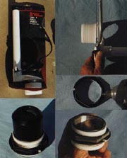
The upper left-hand picture shows the flush valve as purchased. Remove all the hardware from it and cut the threaded section off the valve body (upper right-hand picture). Drill two mounting holes in the flange of the large nut (middle right-hand picture) that comes with the valve. Screw the threaded section into the large nut and use aluminum tape (about four layers at three, equally spaced places) to reduce the inside diameter of the threaded tube (bottom right-hand picture) so that the barrel of a two-inch eyepiece slides in snugly. The lower left-hand photo shows a finished focuser with a 50 mm Plossl eyepiece. Use screws to mount the eyepiece holder to the side of the telescope.
This focuser provides an inch and a half of focusing distance. If you require more, simply purchase a second flush valve and mount its large nut on the opposite side of the telescope's body. Spacers up to one-inch thick can be placed between the second nut and the inside telescope wall to provide as much as three inches of focusing distance. Just make sure the threads on the two nuts are aligned so that as the threaded tube transitions from one nut to the other, it doesn't bind.
THINK MITTENS!
Every amateur astronomy has to deal with the cold. For keeping fingers warm I strongly suggest the use of mittens instead of gloves. Gloves expose twice as much finger surface area to the cold as mittens so they are bound to be colder. Furthermore, gloves isolate each finger's warm from its neighbor's whereas in mittens the fingers help to keep each other warm. All in all, mittens are three times as warm as gloves. Mittens do reduce dexterity so I suggest modifying any knobs, grips, or handles on your equipment so that they can be handled more easily. For very fine movements, like punching buttons on a keyboard, I find a piece of eraser glued to the end of the mitten over an index finger works very well. Writing in mittens takes a little practice but is completely feasible.
80 mm Binocular Light and Dew Shields
By happy coincidence, the inside diameters of the round containers used for many brands of raisins are a perfect match for the outside diameters of 80mm binoculars. This allows these raisins boxes to be used for light and dew shields. Simply use an exacto knife to cut off the bottom of the tubes, run the handle around the inside edge to form a bevel to help force the tube onto the ends of the binoculars, paint the insides flat black, and slip the tubes over the ends of the binocular objectives. An added bonus is that the plastic caps that come with the raisin containers make perfect dust shields. The picture below shows a few of the many raisin box-like containers that can be used to make dew shields.
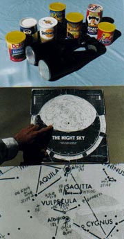
Make Your Own Giant Planisphere!
I was out observing one night when my digital setting circles died. The outing would have been a complete washout except for my trusty planisphere. With it I was able to find enough objects to make the trip worth while.
The next day, I was reviewing my observing notes when it occurred to me that a large-scale planisphere would be useful because it would have enough room to record more objects and show their locations with greater precision. It turned out making such a planisphere was easy. The lower two photos above show what it looks like and provide a close-up of the detail (colored pairs of stars in this case) I can put on it.
I simply took my existing planisphere apart, enlarged all the surfaces using a photocopier, and pasted the paper sections back together on poster board. The new planisphere, now eighteen inches in diameter, had plenty of room for hundreds of new objects. Now, every time I review my observing notes I always mark the positions of the best objects on my giant planisphere. It's an outstanding piece of insurance against the inconsistencies of electronics and batteries.
A Great Dust Cover for Mirror Making
Making a mirror can take months. Between working periods, it's a good idea to cover the mirror with something to protect it from dust and dirt. Large plastic cake holders are perfect for this and can accommodate mirrors up to ten inches in diameter. Simply mount the bottom of the holder on your work station, put your regular padding down followed by the tool and/or mirror. Work as usual (the plastic bottom will catch spills) and when you're done, just slip the cake cover's top over the mirror and snap it tight to the base.
Prescription Eyepieces
The problem with having to wear glasses and do astronomy is that even the long-eyerelief eyepieces (usually only 18-20 mm of eyerelief) don't have the 24 mm of eyerelief needed for most glass-wearers. Fortunately, there's an easy and inexpensive remedy.
Take an old, but unscratched, pair of glasses and use a saber saw to cut a circular section out of the center of one of the lenses to match the diameter of your eyepieces. (ONLY TRY THIS WITH PLASTIC LENSES!) Mount this section in a plastic tube that'll fit over the eyepiece and slide the assembly onto the eyepiece down as close to the lens as possible without touching it. You have now corrected the eyepiece to your vision. The circular section you cut out is small enough to fit inside the orbit of the eye so you can get close enough to the eye lens to see the entire field of view.
Two years ago Sky & Telescope had an ad for a company that would make a Prescription corrector like this for $70.00. It would undoubtedly work better than my solution but then mine is free.
One caution: if you have astigmatism, make sure that you mark the orientation of the lens so that you can line your eye up on it in the correct position.
Wire Spiders
All Newtonian telescope users abhor the spikes produced by the secondary mirror's support vanes. Curved vanes can spread the spikes out so that they aren't visible but they actually diffract more light than straight vanes, with the result that star images are further dimmed and the background has more stray light in it. One way to reduce the amount of light diffracted by spiders is to use very fine wire instead of sheet metal.
The wire spider system in this article consists of three parts: the wires, the secondary mirror holder, and the telescope body mounts. The top center picture below shows a jig used to make the wires, the lower right photo is one end of the secondary mirror holder showing the ends of the wire spiders, and the lower left picture is a telescope body mount.
The wires are sections of thin music wire with loops twisted into each end. The wires are formed on a jig consisting of a length of one by two-inch hardwood with a long bolt sticking out of the side near each end. The distance between the bolts is one-half the length needed for each length of wire, which is determined by the telescope's diameter and the length of the secondary mirror holder. The jig insures that all three spider wires are the same lengths. A loop is twisted in one end of a length of wire, slid onto one of the long bolts extending from the wood spacer, stretched up and around the opposite bolt, then brought back to the first bolt where a second eyelet is formed. Three wires like this are required. Do not paint the wires black because doing can double their thickness and defeat their purpose.
The secondary holder is a length of quarter-inch threaded rod with a wood block threaded onto one end. The block's face is cut at a forty-five degree angle and has the secondary mirror mounted on it with foam mounting tape. A plastic nut is threaded down near the wood block followed by the eyelets at one end of the three wire spiders. A second plastic nut is screwed down to hold the wires in place. A third plastic nut is screwed onto the threaded rod one-inch from the end furthest from the wood block, followed by the eyelets on the loose ends of the wire spiders, and finally a forth plastic nut. Plastic nuts are used because metal nuts can nick the wires and cause them to break.
This picture shows a completed secondary holder for a 1.83 inch diagonal.
To make the telescope body mounts, cut a vertical slice down the center of a quarter-inch diameter bolt using a cutoff wheel on a Dremel tool or a thin bladed hack saw. Make three of these and bolt them to the telescope body. The location of the mounting bolts is calculated from the length of the secondary holder and the required position of the secondary. Once the slotted bolts are mounted, with the slots aligned parallel to the axis of the telescope's tube, thread a plastic nut onto it followed by one of the wire spiders and finally a plastic ball cap, which has had its end drilled out and threaded, round end first. The ball cap is tightened down until the wires are drawn taught and "sing" when plucked. The outer plastic nut is then tightened against the ball cap to keep the wire from slipping.
Collimation is accomplished by gripping the secondary support and pushing, pulling, or tilting it to get the secondary's location correct. The plastic nuts on the body mounts are left loose enough to permit the wires to slide between them during this process then tightened to lock everything in place. The wood block on which the secondary mirror is mounted can also be rotated on the secondary holder's threads.
The final step is to wrap a thin slice of duct tape around the ends of the wires where they attach to the secondary support. This dampens out acoustic vibrations traveling up and down the wires that otherwise can take as long as ten seconds to die out.
I have been using a set of wire spiders based on these plans for an 8-inch, F8 telescope for the last ten years and have enjoyed excellent results with them. The wires are 0.008 inch diameter guitar strings. I found that these wire vanes reduced the intensity of the diffraction spikes by half when compared to standard, 0.020 inch thick vanes. The spikes from the wires were so fine that they could not be detected in stars less than first magnitude. In contrast, regular vanes produced spikes that could easily be seen in stars down to 2nd magnitude.
The wire spider system described in this article is more difficult than a traditional secondary support to install and collimate but for someone truly interested in making a high-performance Newtonian they are the best way to reduce the amount of light diffracted from spiders. Below is a side view diagram of a wire spider setup.
THE BLACKEST BLACK
The photograph above compares, from left to right, light reflected off of flat-black paint, black cloth, sawdust painted flat black, black flocked paper, and black velvet; the most light absorbing material was by far the velvet. Vacuum-like it seemed to suck light out of the air. All the others allowed light, especially grazing rays, to reflect into the optical train. Flocked paper (available from Edmond Scientifics) was the next best and black cloth the third. The test sample on the far left, flat black paint, only looks white because even though it was the flattest black I could find, it still reflected many times the amount of light of the other samples, with the result that it was overexposed in the picture.
NEW!
Black Velvet: is it worth it?
One of the advantages of having a large binocular is that you have two identical scopes for making comparisons. Although the results of The Blackest Black article above clearly shows velvet's superiority in absorbing stray light, it doesn't prove that the expense and trouble of lining a telescope with velvet pays off with darkened backgrounds. To find out if it does, I lined the right-hand scope of my binoculars with velvet. It was a messy, painful, and expensive ($30.00) job. The results? Nil. Nothing. Nada. Zip. I couldn't tell the difference between the velvet-lined scope and the plain old spray-paint-over-cardboard scope. The velvet scope certainly looked darker in the daytime, but at night it didn't provide any increased contrast.
Coated versus Uncoated Eyeglasses for Observing
I compared glasses coated with an antireflective coating to those with no coating. I found that the coated glasses gave me an extra quarter of a magnitude of brightness as far as how dim a star I could detect. Please note that the coating in this test was the commercial type offered by eyeglass manufacturers, not the high-quality antireflective coatings available from companies that coat telescope objectives.
The Wire Test
Telescope Making magazine published two articles about the wire test for large, fast telescope mirrors. I tried using it on a 13.1 inch, f4.47 mirror using a 0.0006 piece of cat fur as the wire. Even with this fine a wire, the shadow zone on the mirror was far to wide to be used for effective testing. Also, the shadow jumped around a lot. It seems that the test is extremely sensitive to vibrations. It would seem the wire test is only good for very large mirrors that are faster than f4 and mounted very firmly.
Conquering the Foucault Zone of Uncertainty
In How to Make a Telescope, Texereau promises that it's possible to achieve repeated knife-edge readings in the Foucault test that differ by only a few thousandths of an inch. Even after eliminating backlash in the tester's adjusting screw many mirror makers get frustrated because their readings still vary by three times this amount. Fortunately, there's a simple remedy.
During Foucault testing the human eye is limited in determining when two shadows are the same brightness. On either side of the exact knife-edge position where the shadows are precisely equal is a range of knife positions where the eye thinks the shadows are equally bright even though they aren't. This "zone of uncertainty" is a major source of reading variations. Outside this zone the differences in shadow brightness are noticeable. Within it all the shadows look the same regardless of the knife-edge's location. Practice trains the eye to detect smaller shadow differences thereby reducing the zone of uncertainty but it can never be completely eliminated.
Increased accuracy can be achieved by taking two sets of readings: the first with the knife edge starting closer to the mirror than its anticipated final position, and the second with the knife edge starting further from the mirror than the anticipated final position. The resulting two groups of readings define the near and far boundaries of the zone of uncertainty. The point halfway between the averages of these two groups is the exact knife-edge position where the shadows really are the same brightness.
I found that using this technique increased my accuracy and precision from plus-and-minus 6 thousandths to 2 thousandths.
COLLIMATION DOTS
Don't believe that Newtonian secondary mirrors shadow collimation dots painted on the primary mirror's center. At low power, the true field of view angle is wide enough so that these dots are illuminated and can therefore degrade image quality through diffraction effects and, if they are white, by reflecting light into the eyepiece. Reduce the second effect by using dark paint. If this makes it too hard to see, shine a laser pointer on it.
NGC Object Sizes
Designing a telescope for a specific class of objects allows the design to be fine-tuned for maximum performance. This optimization requires knowing the size distribution of objects to determine secondary mirror and baffle diameters. The following information is provided to assist anyone designing a telescope for a specific size of object. It is a condensation of information provided on 1866 NGC objects discussed in Burnham's Celestial Handbook. All dimensions are maximum dimensions.
115 planetary nebulas divided themselves into 13 less than 5 seconds of arc across, 28 from 5 to 10 seconds, 25 from 10 to 20 seconds, 12 from 20 to 30 seconds, 19 from 30 seconds to 1 minute of arc, and 18 from 1 minute to 1 degree in diameter.
1281 galaxies broke down to 184 less than 1 minute of arc in diameter, 981 ranging from 1 to 5 minutes, 88 from 5 to 10 minutes, 17 from 10 to 20 minutes, and 11 greater than 20 minutes of arc in diameter.
103 globular cluster grouped themselves into 3 less than 1 minute of arc, 60 from 1 to 5 minutes, 29 from 5 to 10 minutes, 8 from 10 to 20 minutes, and 3 greater than 20 minutes in diameter.
77 of 279 galactic clusters were less than 5 minutes in diameter, 92 were 5 to 10 minutes, 64 were 10 to 20 minutes, 36 were 20 to 40 minutes, 7 were 40 minutes to 1 degree, and 3 were 1 to 2 degrees in diameter.
Finally, 88 bright diffuse nebulas arranged themselves into 31 from 1 to 5 minutes, 9 from 5 to 10 minutes, 14 from 10 to 20 minutes, 9 from 20 to 40 minutes, 5 from 40 minutes to 1 degree, 10 from 1 to 2 degrees, and 10 greater than 2 degrees in diameter.
This analysis shows the ranges of true angles for most of the objects accessible to amateur astronomers. When combined with the designer's own goals and optimization criteria, this information will enable determination of the best diagonal, baffle diameters, and eyepieces.
Homemade Ronchi Gratings
It's easy to make ronchi gratings at home using a computer. Simply access a drawing program and create a series of fifty parallel lines. Set the line width to "hairline" or the narrowest available and move the lines as close to each other as the computer allows. Next, use the "select all" and "group" functions to make all the lines a single object. Finally, select this object and use the cursor to shrink it to give the lines-per-inch count desired. Print this out on transparency stock or on plain paper and go somewhere that can do transparency copies and have them make a transparency of it.
The quality of the results depends on the printer used. Vertical lines are sharper than horizontal lines on laser printers and are straight enough to evaluate surface smoothness. Horizontal lines are better than vertical lines on ink jet printers but both are rough and only good enough to evaluate the general shape of a mirror's surface.
Regardless of the printer used, digital artifacts in line spacing will result in clumping of the lines into three, four, or five-line groups in gratings finer than 100 lines per inch. These have no effect on the grating's usefulness because these groups are still larger than the light cone near the focus where most testing takes place.
This is just a start. I have a dozen other articles that will be added in the near future. Please come back often to see what's new.
Off-Axis Paraboloid Work
I spent 18 months, testing many different techniques of trying to figure an off-axis paraboloid onto an 8-inch, f8, spherical mirror. Over a dozen times I worked ten waves of astigmatism into it only to have to spend days refiguring it back to a sphere because the technique I was using didn't work. This night, 16 February 2001, I had to accept that I couldn't do it for two reasons. First, one of my requirements was that the mirror had to be tested simply, without recourse to nullying mirrors or lenses. I could not accomplish this. I could not find a way to measure the corrections using a Foucault tester or ronchi gratings. Without measurement I could not claim to have made the correct figure. Without measurement, it's not science... just guessing. Second, I demanded that the figure was smooth. It makes no sense to make an off-axis mirror to avoid the 10-percent degradation in image quality the secondary and spiders cause if surface roughness causes a 20-percent degradation. Every technique I tried caused excessive surface roughness. This may be unavoidable using non-symmetrical strokes. Just as a paraboloid will never be as smooth as a sphere, when made with the same skill, so an off-axis paraboloid, made without warping and symmetric strokes, may be predisposed to being rougher than a symmetric paraboloid.
To say I'm disappointed would be an understatement. However, the stars are still there and I have other telescopes that are great to use so perhaps things aren't so bad after all.
I would be remiss if I didn't use this opportunity to plug the two best sources for information on telescope making. Here they are:
AMATEUR ASTRONOMY: http://AmateurAstronomy.com
Amateur Telescope Making Journal: email [email protected]
![]()